
 en
en de
de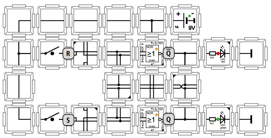
Flip-flops for dummies – part 2
For dummies
For those of you who liked the Brick’R’knowledge blog post series “for dummies” are going to like this new blog post as well. As always, I write this post being a complete beginner myself. This time, I will be dealing with RS flip-flops, D flip-flops and JK flip-flops. I advise you to read the former posts about the topic of “Logic” that describe the basic gates and provide a general explanation of flip-flops.
„Easy“ – the RS flip-flop
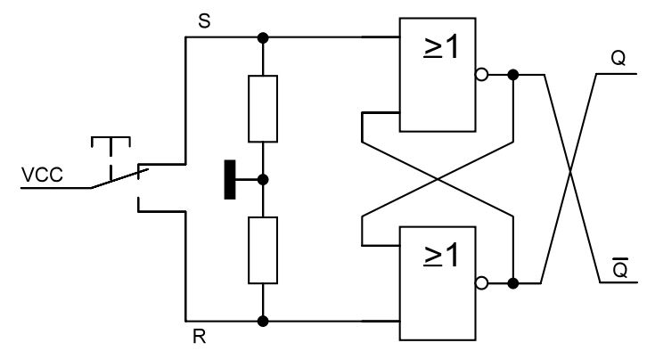
According to its definition, the RS flip-flop is a simple, not synchronous flip-flop (you find more information on that topic in our blog post “Flip-flops for dummies part 1) that can be built out of two NOR gates – which is why we call it NOR flip-flop. You could also build it out of two NANDs. In this case, you would need negated inputs, though. The following picture shows you the RS flip-flop with two gates: the NOR gates’ outputs are connected to one of the inputs of the respective other. You can print out this circuit diagram and consider what will happen if you push a button. I advise you to use two pens of different color and a NOR truth table.
The circuit symbol of an RS flip-flop looks like this:
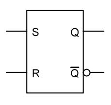
The inputs are called S and R. S meaning “set” and R meaning “reset”. Q is the output and /Q is the negated output. In the field of “Logic”, this is generally indicated with the little circuit that is placed next to /Q. You will find this little circle also on our bricks’ labels and on the circuit diagram.
It’s logical – the truth table
So-called truth tables clearly represent how flip-flops function. When conveyed to a Brick’R’knowledge circuit, this means that there is a 1 at the inputs of S and R when pushing a button. The connection is closed now. Regarding the outputs Q and /Q, 1 represents the LEDs flashing. Regarding the 0 at the outputs S and R , it represents not pushing the button and when there is a 0 indicated in the truth table it means that the LED does not flash at the outputs Q and /Q. Let’s have a closer look at the truth table:
![]()
What happens in practice?
Let’s start with a RS flip-flop brick circuit consisting of two NOR bricks that you can build yourself in order to directly implement my description:
Careful: For practical reasons Q is below and /Q above which is reverse from the circuit symbol and diagram of the RS flip-flop.
When I push the S button, the LED starts flashing at Q (or, in case S has been pushed directly before, the LED does not change condition 1) but even more important: the LED keeps flashing. As I mentioned in my last blog post, flip-flops have a “past” and not only a “present”. If I had a simple logic gate consisting of one gate only, the LED would not keep flashing meaning that the information “LED flashes” would not be saved. When I push the R button, the condition Q will be reset to 0, meaning that the LED turns off (or, in case R has been pushed directly before, the condition 0 does not change). When S had been pushed and the LED flashes at Q, I can keep on pushing S as long as I want – the condition stays the same. Logical but also important: If I don’t push a button, meaning R and S are 0, the condition stays the same. This simply means that there won’t happen any automatic change if I don’t push the button. Visually speaking, a rocker does not pull to one side without outside influence. Here is another interesting fact: when S and R are being pushed simultaneously the flip-flop does not „know“ for which one to decide. This is why this condition is prohibited. Speaking didactically more correct, the successor state is undefined as it is not clear which output will be “1” at first. In our next blog post we will get to know the D flip-flop that provides a solution for the problem concerning the “prohibited condition”. When you look at the output /Q, the conditions 1 and 0 simply turn.