
 en
en de
de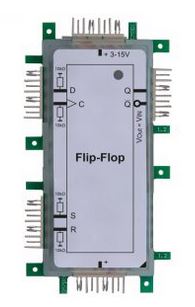
Flip-flops for dummies part 1
For dummies
For those of you who enjoyed our blog post series “for dummies” so far will be happy to learn that this will be a new one regarding the matter of “flip-flops” and logic. Being a dummy myself I will have a look into three different flip-flops: RS flip-flop, D flip-flop and JK flip-flop. As “logic” is a pretty complex topic, my advice is to start reading the first two posts on logic that explain the elementary gates. You can read the second part “Flip-flops for dummies part 2” next week.
Trying to explain abstract manner in a practical way
When I am being asked about the difference between a simple standalone logic gate and a flip-flop, I usually say: “A flip-flop has its past”. I’m not sure whether this is correct electrotechnically or didactically speaking. What I mean is that you know what is going to happen when activating a switch that is connected to the input of an AND gate – even if you don’t know its previous state. The difference regarding a flip-flop is that it remembers the previous state and does not return to its initial state. When I activate switch 1 that is connected to the input of a flip-flop, I cannot precisely tell what is going to happen if I don’t know the original state (for example, LED 1 turns on, LED 1 turns off, LED 1 stays on, LED 1 stays off). A flip-flop can store 1 Bit: This means, it can remember either “1” or “0”. In this case, the example of a rocker is pretty common: one end of the rocker goes up while the other end goes down. Usually, it is not in a horizontal position, as there will always be a breath of wind destroying this “metastable” condition. With regard to the flip-flop this cannot be a breath of wind, of course, but a little difference in the type of construction, for example. When the right end of the rocker is down and I try pushing it down nevertheless, I won’t change anything as the condition has already been stored. There will only be a change when I push down the other end of the rocker.
Edge triggering exemplified by garden lighting
We already know from previous blog post that electronics is never really easy – which is why it gets more complicated now. Let’s assume our flip-flop has 2 inputs and 2 outputs. We call the 2 inputs x and y and the 2 outputs Q and /Q. When activating the switch of a RS flip-flop each information is directly passed on. However, there are also status- and edge controlled flip-flops. Here is an example (not very creative, though): You and your flat mates have garden lighting which is supplied by solar energy. You have a switch in your living room with which you can turn the garden lighting on and off as you only need it when it is dark outside. So far, this would be a description of a RS flip-flop. Yet, you can only produce power in summer with sufficient solar radiation. This is why there is a second switch with which you can control whether the lighting should be active at all. If this switch is turned off during winter, the lighting won’t turn on, no matter what you do. There won’t happen anything without the upstream “summer/winter switch”, no matter if you activate the “day/night switch” or not. With regard to an edge triggering flip-flop this means: If there isn’t any change of condition at the clock input, activating the switch has no effect on x or y. A status-controlled flip-flop does not react on a change at the clock input but simply if there is a special signal level. One specialty at the end: Regarding a double flank flip-flop, the clock input recognizes the information, for example, „1“ and only passes it on during the next change of signal level. Regarding the single flank flip-flop, this happens in one part.
For definition lovers:
You could probably express everything we have learned so far in a much more sophisticated way. Below, you’ll find the definitions of each individual flip-flop:
- Not edge triggering flip-flop:
Flip-flops without clock input are completely independent of timing. S and R can be addressed anytime.
- Status-controlled flip-flop:
1S and 1R of a status-controlled flip-flop are effective only as long as there is a signal level at the clock input (C1).
- Single flank flip-flop:
Regarding the single flank flip-flop 1S and 1R are only effective when changing the flank at the clock input C1. The susceptibility to faults is reduced. Controlling the clock edge is indicated by the circuit symbol of a triangle.
- Double flank flip-flop:
The double flank flip-flop receives the input status of the first clock edge and issues it with the following clock edge. The susceptibility is minimalized. Controlling the clock edge is indicated by the circuit symbol of a triangle.
We call flip-flops „Master-Slave-Flip-Flops“ if their input status appears delayed. The circuit symbol shows this at the right angle of the output. The so called JK-Master-Slave-Flip-flop is a popular type of its kind.
Next time
In the next blog post we will be dealing in more detail with the RS flip-flop, the D flip-flop and the JK flip flop and will have a look into the matter of shift registers.