- Sets

Relay (NOT operation)
relay
Julia Bauer
English
Advanced
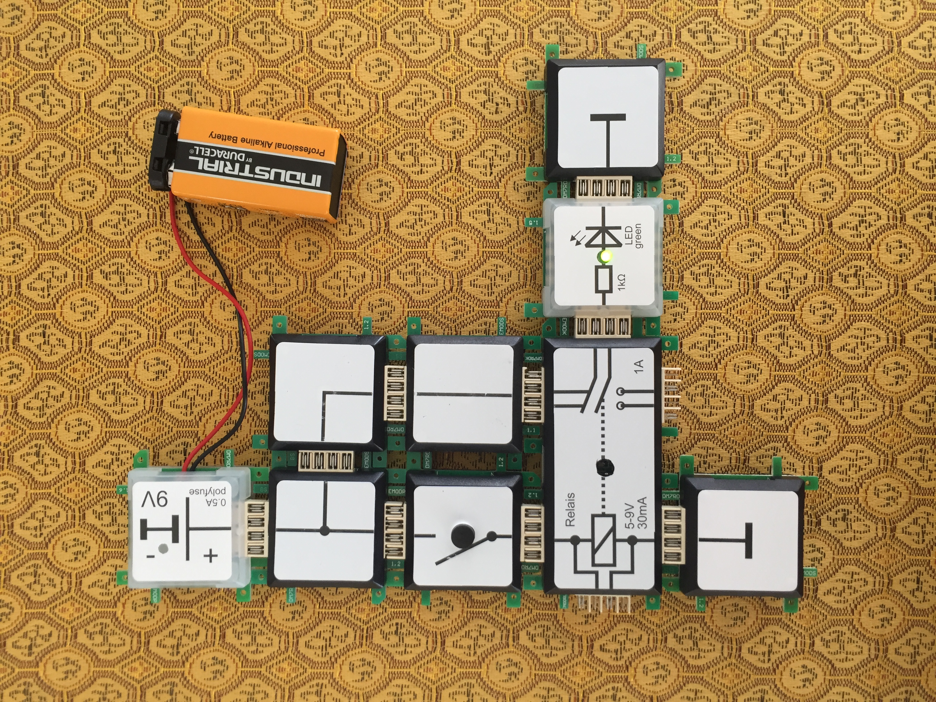
In circuit 18.7 we talked about to the use of relays in early computers. In the arithmetic unit of a Zuse-Computer, NOT functions have been implemented similars as we will do in the current experiment. The high level at the output is always present if the button has not been pressed. The input signal of „0“ results in an output signal of not „0“, which is „1“. Only two states are possible: „0“ and „1“. An input signal of „1“ results in an output signal of not „1“, which must be „0“. The red LED indicates the output level. Note: In digital technology the „L“ and „H“ are used to identify the level. These can be assigned to different logical levels depending on the technology used. The most common denitions for a level range and the assignments are:
• « L“ corresponds to 0 eg 0V to 0.8V and „H“ with >2V corresponds to 1, for example with standard TTL logic. Any voltage values
inbetween are undened.
• « L“ corresponds to 0 eg. 0V to 0.7V and „H“ with >1.7V corresponds to 1, used for 2.5V CMOS logic.
• « L“ corresponds to 0 eg. <-1.4V and„H“ with>-1.2V corresponds to 1, used for ECL-logic. Values inbetween are undefined.If the „L“ is assigned to a „1“ instead of a „0“ and „H“ to a „0“ instead of a „1“ this is called a negative logic, otherwise its a positive
logic.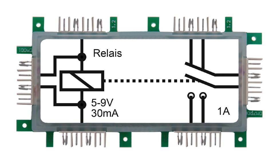
Art. 118367
Anzahl: 1
Art. 113629
Anzahl: 1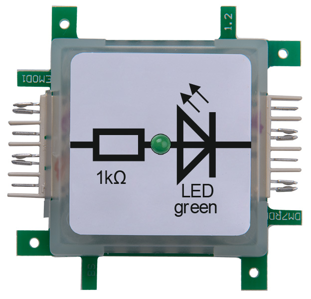
Art. 113639
Anzahl: 1
Art. 113644
Anzahl: 1
Art. 113632
Anzahl: 1
Art. 113630
Anzahl: 2
Art. 113631
Anzahl: 1
Art. 113633
Anzahl: 1